I have received an interesting project that I thought I would post. If anyone has seen anything that resembles these High Butterfly throttles please let me know.
The story goes that these throttles were attached to a display board. The current owner has had them for about 10 years and the prior owner bought them on the same display board and owned them for at least 20 years. That owner also bought them on the display board and owned them for an unknown period of time. Any history before that is unknown. A Bosch competition injection pump accompanied these throttles and was sent to Gus Pfister at Pacific Fuel Injection for restoration. According to Gus it is the oldest competition pump of its kind. The date code on the pump is September 1968.The throttles have had moderate use as evidenced by the worn bushings and small grooves in the barrels. The throttle shafts are still in good shape and other wear areas are not that bad so they haven't been beat to death like a lot of them.
When I first looked them over I thought someone had modified a set of the 2.5 throttles, but I couldn't figure out how they would have re-sleeved them to 44mm on top and about 40mm on the bottom. They don't look re-sleeved. There are also some crude areas on the castings and even some differences from one throttle housing to the other. It soon became apparent that these are factory throttles, but what their application was in the day is unknown. They look like they were used for developmental purposes. The later throttles were improved in many ways. Were these the very first High Butterflies?
Housing details
The housings had been painted black as was some of the hardware. Here are some details after they were disassembled and the paint removed.
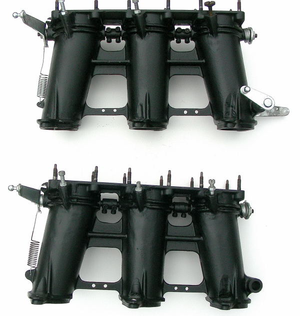
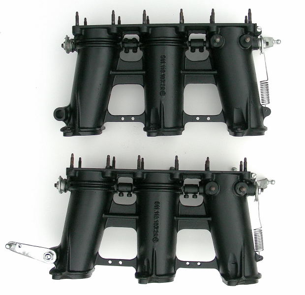
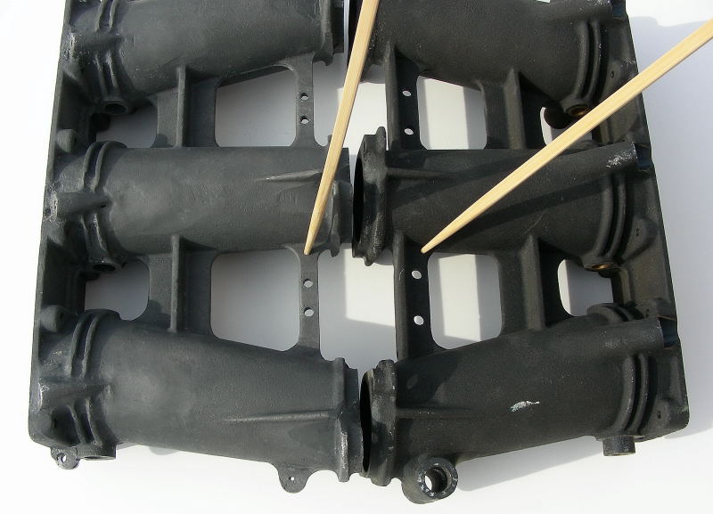
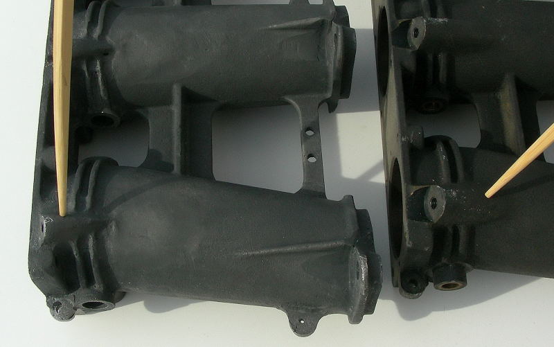
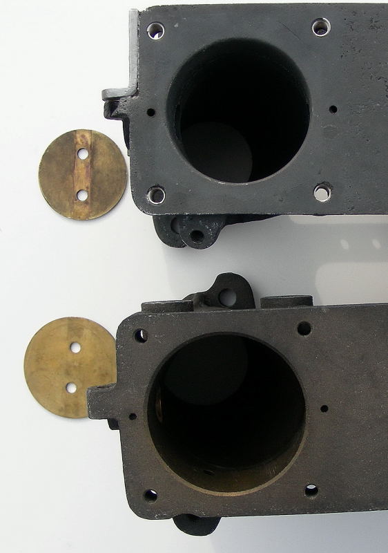
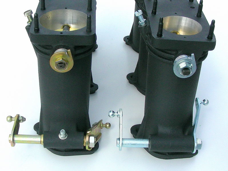
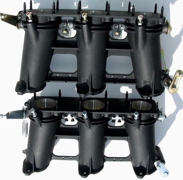
First picture shows the housing differences compared to a production housing. The prototype housing on the left has a narrower support rib. Both are magnesium.
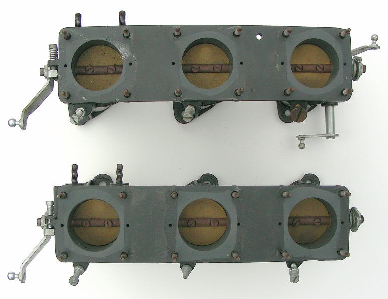
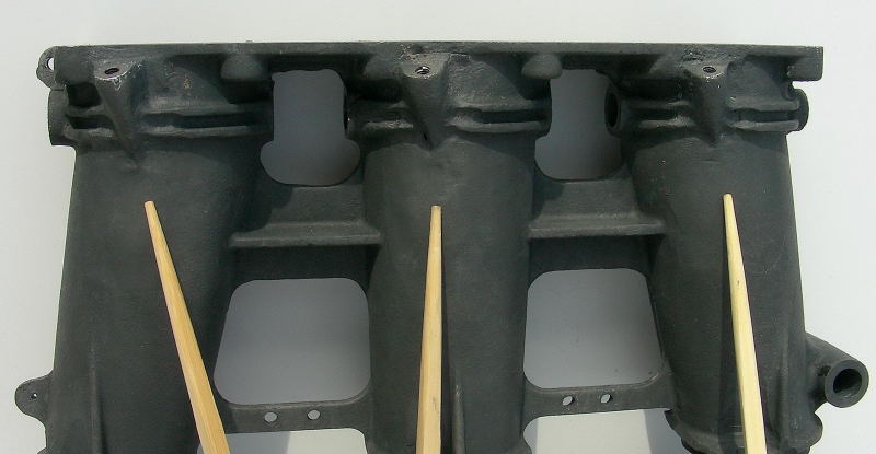
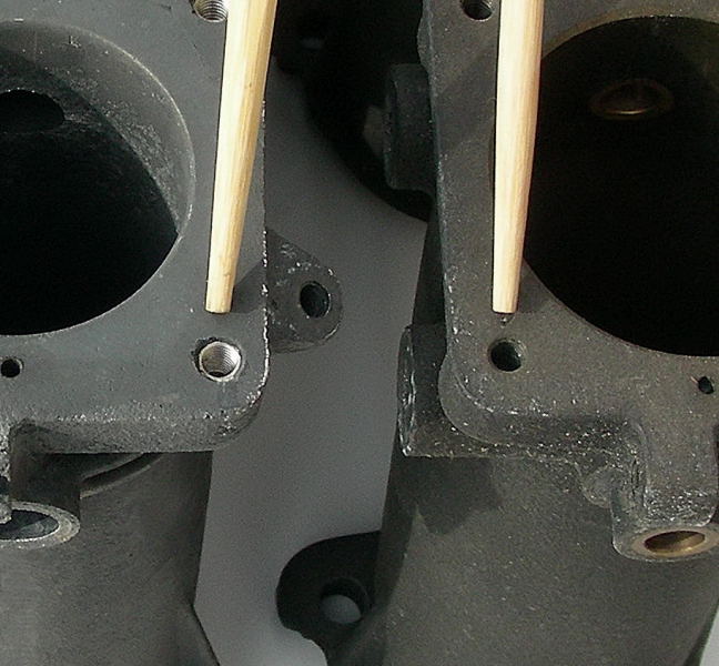
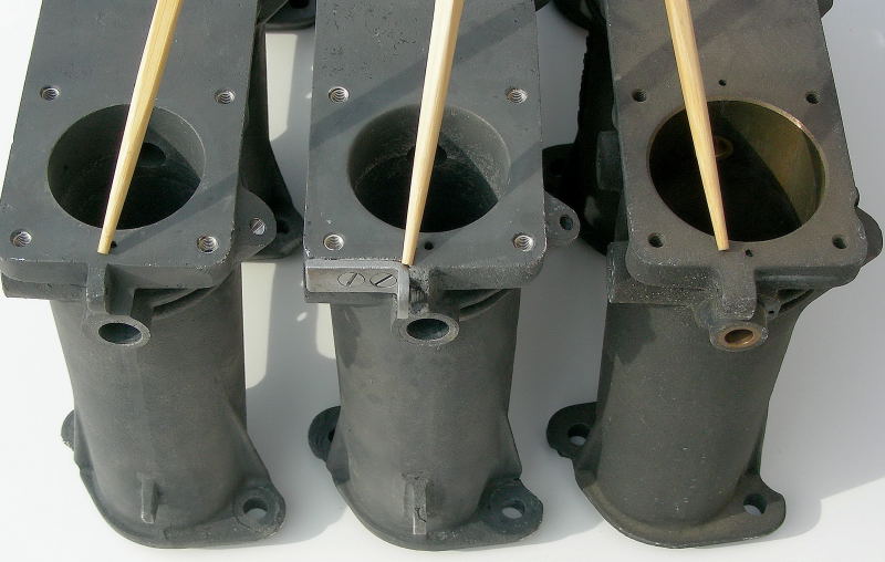
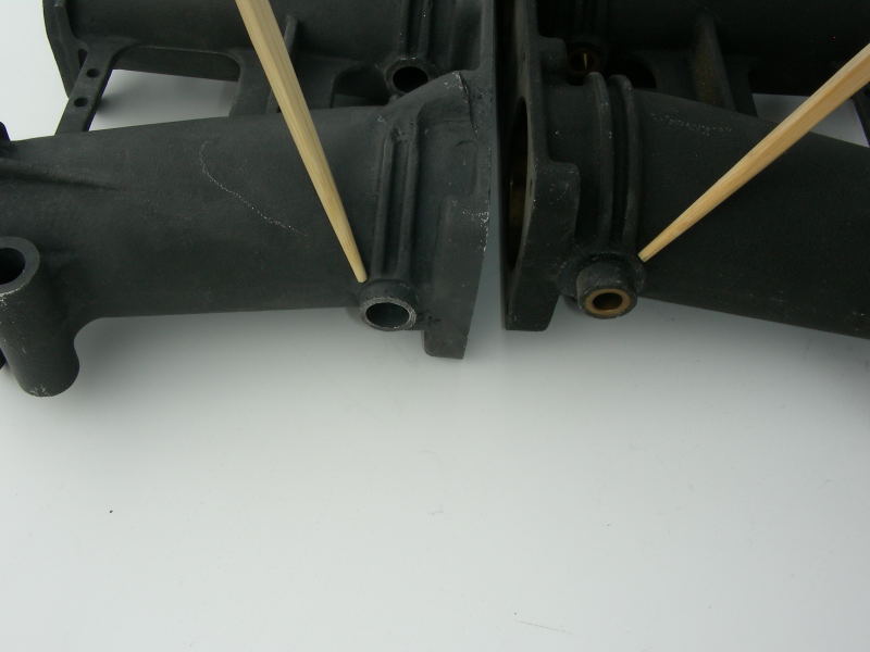
Second and third show the casting around the air screws. This area looks like an afterthought. The fourth picture shows a production version for comparison. Thread for air screw is smaller (5mm) compared to 6mm for the production housing.
Last pictures shows the steel insert for the top studs. Production version has no insert.
More Housing Details
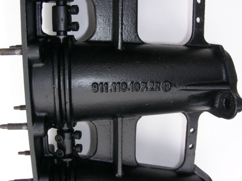
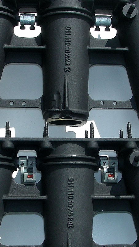
The castings look to me like they were made in a mold and then the air holes were added on later. The diameter of the air holes are 2.9mm on one housing and about 3.7mm on the other. So it looks like they were still learning at this point. The production holes are 3.9mm. (2R and 5R)
I don't know of other castings, only the 2R and 5R. What I find interesting is the castings numbers can stay the same but the castings can be different. For example, both the RSR and the SCRS were 911 110 107.5R castings. The SCRS had an extra boss for a throttle stop at WOT and the RSR did not. Also the SCRS had the cold start holes on the sides. I believe the throttles pictured here were the early developmental version which became the production 2R for the 2.5 ST
Here are more details.
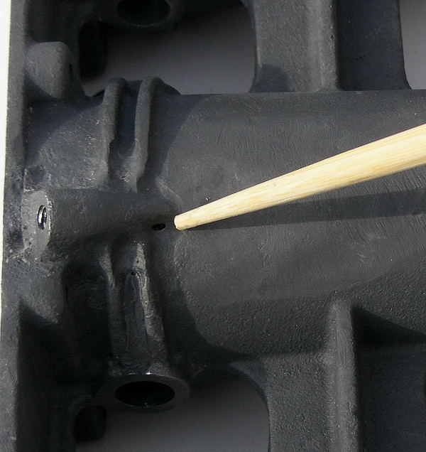
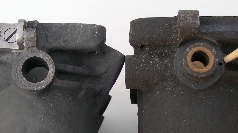
Picture 1: Production housing on right has a small hole for the return spring. Prototype with no hole and repair done to broken throttle return screw boss.
Picture 2: Spring hook on both prototypes. Getting them to look the same was not important.
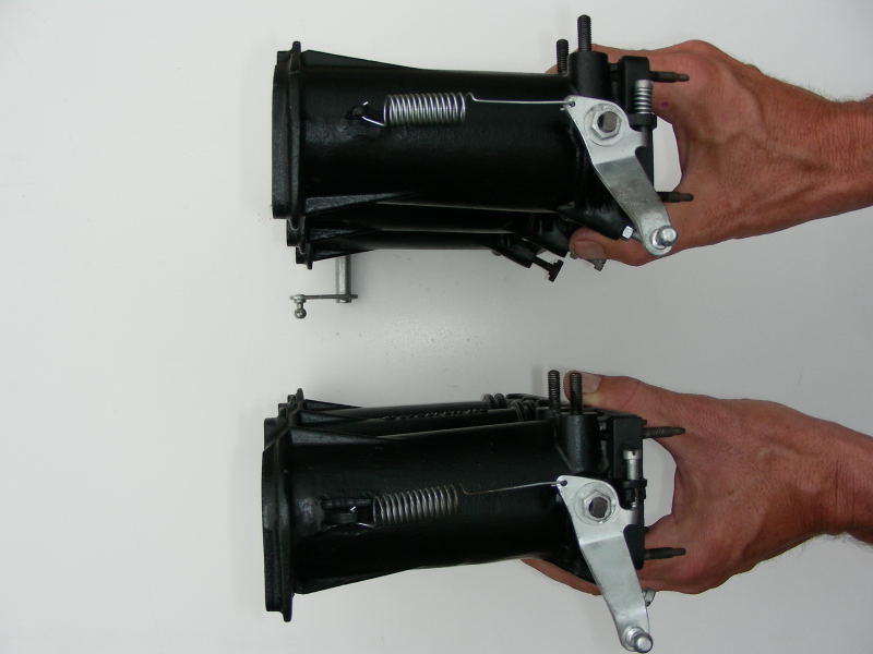
Picture 3: Top housing 44mm, Bottom housing 50mm (production)
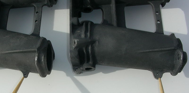
Picture 4: It appears that they learned to make the throttle return boss a little thicker (right side production housing).
Picture 5: Details of rear of the housings. Bushing removed on prototype, left.
Hardware Detail
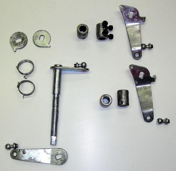
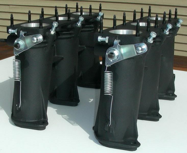
The throttle shaft couplers are a barrel type similar to what was used on a 3 barrel Weber carburetor. They are a bit different than the Weber coupler in that they are welded around the middle to make them rigid. Initially I thought they had been replaced at some point because these are different than the production type. But if you look at the throttle shafts they have no roll pin hole to secure the production type coupler so I've concluded that these are original couplers for the throttles. You can also see the marks on the shafts left by the set screws. The down side to using these couplers is that they don't work well if there is any shaft misalignment. The two piece couplers used on the production throttles solved that problem.
Picture 1: Misc hardware. Note the crude barrel type shaft couplers. Throttle arms with peened on ball pins rather than the threaded type.
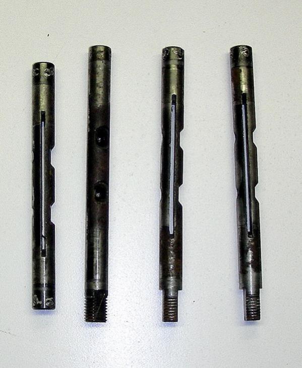
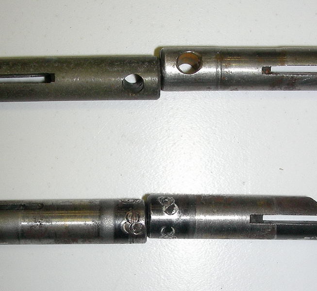
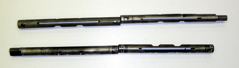
Picture 2: Original throttle shafts. Note the marks on the ends from the coupler set screws.
Picture 3 and 4: Production throttle shafts top (roll pin holes). Prototype shafts below.
|
High Butterfly PrototypeAfter pictures/comparison
|